Installation of Toshiba Injection Molding Machines
1. Outline
This manual defines the installation procedure of electrically driven injection
molding machines for delivering them to the customer under optimum condition.
2. Application
This manual applies to EC30SXⅡ-EC230SXⅡ series injection molding machines.
3. Work Procedure
3-1 Mechanical unit
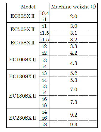
3-2 Machine weight
Refer to the following list for machine weight.
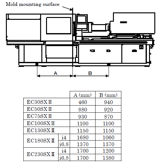
3-3 Li f t ing positions of forklift
When moving the machine by a forklift, set forks at A and B positions and lift the machine.
3-4 Electric parts and equipments
(1) Connection of power source
Observe the following precautions to connect the power source.
(a) Check for correct wiring since wrong connection may reverse motors. You
may check the wiring with direction of nozzle movement.
(b) Check terminal blocks and cable connectors of electric equipments for loose
bolts.
(2) Precautions (as per instruction manual)
(a) Grounding work
Complete grounding work. Installation grounding of resistance below RΩ.
R=100Ω at ≦AC300V
R=10Ω at >AC300V
(b) Installation of circuit breaker
Install a circuit breaker on the power side of or inside the power switchboard. The circuit breaker should be of medium-sensitivity and high-speed type (100 mA) to meet inverter, or equivalent type.
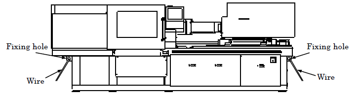
4. Fixing way of machine at transportation
Fix the machine by using wires through fixing holes of machine frame at clamping end face and injection end face.
5. Hazard Warnings
(1) Never enter the area under the machine being lifted with a crane.
(2) Do not remove fixing bolts of injection and clamp units before installation is completed.
(3) Do not perform other work not related to body mounting before installation is
completed.
Safety of Toshiba Injection Molding Machines
1. Three Principles Regarding Safety
Since the injection molding machine allows large mold clamping and injects melted resin at high temperatures, unexpected contingencies can occur. However, contingencies can generally be prevented through the daily checking of safety devices and proper operation. The structure, function and safety features of the machine must be thoroughly understood prior to machine handling, operation, and maintenance.
Strictly observe the following three safety rules to operate the machine safely.
[1] Be absolutely sure that the safety gate is opened before placing your hands into the mold.
[2] Always be sure to turn OFF the power supply before placing the upper part of your body or entering between the mold platens. [3] Do not touch any moving portion of the machine.The above three safety principles are the most important regarding safe operation.
These principles should take precedence over all others.
Please contact our service department if there are any points in this instruction manual which are not completely clear.
2. Safety Precautions
2.1 Precautions before Operating
2.2 Precautions for Injection
2.3 Precautions for Clamping
2.4 Precautions for Electric System
2.5 Safety Precautions for the Use of Hoses
2.6 Noise level
2.7 Nozzle Selection, Assembly and Disassembly
2.8 Auxiliary Equipment
2.9 Exhaust System
2.10 Other Precautions
3. Modifying the Injection Molding Machine
The electrical circuits of this injection molding machine are equipped with interlocks to secure the safety of the machine operators. As unapproved changes of these circuits may result in bodily injury or damage to the machine, always contact TOSHIBA MACHINE CO., LTD. before attempting any modifications.
TOSHIBA MACHINE CO., LTD. will not be responsible for any accidents caused as a result of unapproved modifications to the machine, especially regarding parts related to safety and electrical circuits.
4. Safety Device
This machine is provided with electrical safety devices, mechanical safety devices, emergency stop buttons, and the purge shield.
4.1 Electrical Safety Device
4.2 Mechanical Safety Device
4.3 Emergency Stop Button
4.4 Purge Shield
5. Safety Plates
6. Locations of Safety Devices and Plates
Preparation and Operation Procedure
1. Outline of Injection Molding Machine
1.2 Control Station of INJECTVISOR
1.3 Mechanical Configuration and Movement
1.3.1 Injection Unit
1.3.2 Clamp Unit
2. Preparation for Operation
2.2 Inspection Prior to Starting Operation
2.3 Starting the Machine
2.4 Mold Set-up
2.4.1 Preparation
2.4.2 Replacement of Ejecting Rods
2.4.3 Mold Mounting and Die Height Adjustment
2.4.4 Detect Circuit of Ejector Plate Retract
3. Adjustment and Setting of Machine Units
3.1.1 Setting of Clamping Force and Low Clamping
3.1.2 Setting of Mold Open/Close Speed and Speed Shift Position
3.2 Setting of Ejection Controller
3.2.1 Setting of Ejection Mode and Count
3.2.2 Setting of Ejector Stroke
3.2.3 Setting of Ejection Speed
3.2.4 Setting of Ejection Force
3.3 Adjustment and Setting of Barrel Controller
3.3.1 Setting of Barrel and Nozzle Temperature
3.3.2 Precautions for Temperature Setting
3.3.3 Modification of Barrel Temperature control
3.4 Setting of Injection and Charge Controller
3.5 Setting of Nozzle Controller
3.6 Setting of Timers
4. Operation
5. Graphs for the Injection Speed and Pressure
Alarm Code List and Error Resetting Procedures
Maintenance and Inspection
1. Prohibited Operations
2. Inspection Prior to Operation
3. Daily Inspection
4. Periodic Inspection
5. Replacing the Screw and Barrel
5.1.1 Swiveling the Injection Unit
5.1.2 Replacing the Screw
5.1.3 Replacing the Barrel
5.2 Replacing the Heater Fuse
5.3 Plastic Parts and Rubber Parts Recycle
6. Maintenance and Inspection
6.2 Timing Belt Inspection
6.2.1 Check Points of Belt Tension
6.2.2 Inspection Method of Belt Tension (Check by Tension Meter)
6.2.3 Inspection Method of Belt Tension (Check by Press Force)
6.2.4 Visual Inspection
6.2.5 Check for Belt Dislocating
6.3 Inspection for Lubrication
6.3.1 Inspection for Lubrication
6.3.2 Replacing the Grease Cartridge
6.3.3 Forced Grease Mode
6.4 Heater Maintenance and Inspection
6.5 Inspection for Barrel and Check Ring Wearing
6.6 Inspection for Load Cell
6.7 Cleaning of Air Filter
6.8 Cleaning the Inside of Control Cabinet