Hydraulic Motors and Cylinders of Injection Molding Machine – By Zafar Kamal Hydraulic motors are used to convert hydraulic energy (pressure and flow) to mechanical energy. Their operation is reverse of a pump’s. When oil is pushed into one port and discharge from another , the motor rotates in one direction. If the flow is reversed, the direction of the rotation is reversed. Since no centrifugal force exists until the motor begins to rotate, springs are used behind the vanes to hold them in place against the ring. Unlike motors, cylinders are linear actuators which convert hydraulic energy into mechanical energy. Oil forced in the one end of the cylinder causes the piston and rod to move in one direction. If the flow of oil is reversed the movement is reversed.
Read more →Operating Valves and Control of Hydraulic System for Injection Molding Machine – By Zafar Kamal The relief valve limits the maximum pressure in the hydraulic circuit. Since the pump is a positive displacement unit, it continuous to push out oil regardless of the resistance which the flow encounters. The relief valve is needed to bypass excess oil back to the tank and protect the hydraulic system and machine against excessive pressure. An unloading valve is used to dump the flow of oil from one pump, while holding pressure with another pump. This type of pump is generally used with a double pump to conserve power and heat by unloading the large-volume pump while holding pressure with the small-volume pump. A check valve permit flow in one direction and prevents flow in the other direction. A light spring hold the poppet on its seat. When the pressure on the inlet port overcome the spring force, the poppet lifts off its seat and flow passes from the inlet to the outlet port. In the reverse direction, pressure applied
Read more →Hydraulic Pump of Injection Molding Machines – By Zafar Kamal The pump pushes the fluid through the lines. The pumps most commonly used on injection-molding machines are the balanced-vane type. The pumping unit of cartridge includes a cam ring, a slotted rotor, and vanes held between, with a wear plate and pressure plate at the sides. Pockets are formed by each two adjacent vanes, the ring rotor, and the side plates. As the pump rotates, the volume of each pocket become larger or smaller as the contour of the cam ring pushes the vanes in and out of the rotor slots. Ports in the side plates, connected to the pump inlet port, admit oil into the rotating cartridge to fill the pockets as they increase in size. Other ports in the sideplates are connected to the pump discharge port and accept oil discharge from the rotating cartridge when the pocket decrease in volume. Two inlet ports are diametrically opposite each other, as are the two pressure (outlet) ports, to provide the hydraulic balance which eliminates all
Read more →Hydraulic System for Injection Molding Machines – By Zafar Kamal The function of the hydraulic system in injection molding machine is to transmit the power from electric motor to the various moving parts of the machine, and to control the power. An electrical control system regulates the hydraulic system to control the direction, force, speed, and sequence of the machine cycle. The basic components of the hydraulic system are: 1-fluid reservoir 2-pumps 3-valves 4-cylinders 5-hydraulic motors The hydraulic fluids transmits the power throughout the hydraulic system, and lubricates the pumps and valves. It is important to follow the recommendations of the machine manufacturer or the hydraulic-equipment supplier in selecting the fluid to be used. The hydraulic lines form passageways in which the fluid from one component to the other in the circuit. The lines may be seamless steel tubes, hoses, or the hydraulic oil may flow through drilled manifolds. The reservoir is simply a storage tank for the hydraulic fluid. In addition, it helps to keep the fluid clean by allowing contaminants to settle out, and
Read more →Opening and Closing System for Mold in Injection Molding Machines – By Zafar Kamal Opening and Closing System for Mold The function of the clamp end of an injection molding machine is opening and closing of the mold. At the same time it must have a means of keeping the mold tightly closed during the injection cycle. This function is performed by a mechanical or hydraulic device for traversing the movable platen of the machine. Mechanical devices for moving and locking the movable platen consist of toggle systems which can be single or multiple, mounted between the movable platen and the fixed tailstock of the clamp unit. With the toggle in the open or folded position the movable and stationary platens are separated and the mold is open. When the mold is closed the toggle arm form a continuous beam structure that can support the full clamp force of the machine. Clamp systems can be also be direct hydraulically operated. Hydraulic clamp cylinders can develop large clamp forces but they are slow acting as compared with
Read more →Efficiency of the Clamp in Injection Molding Machines – By Zafar Kamal The nominal clamp-force ratings are approached but rarely reached in actual molding machines. A particular unit may be designed for a specific strength factor but more than likely it will not have the exact force indicated. Since, in the course of any design calculation, there are many add-on factors which will indicate the need for more clamp force than the theoretical value, any loss i efficiency can usually be neglected . Also, as the machine is used its efficiency will continue to fall off from its original rating. Therefore, any machine that has been in operation for any length of time should be considered as having a lower clamp force than when it was new. If calculations indicate that the clamp force of a machine may be taxed by a particular job, other avenues should be sought for the running of this job. One approach can be redesign of the mold to require less clamp force by reducing the projected area. The other one
Read more →Clamping System Rating of Injection Molding Machine – By Zafar Kamal The clamping system for the injection-molding machines have nominal ratings in tons of clamp force that can be exerted. Although machines are built to certain standards to provide a given force, individual units can vary somewhat from their design ratings. A large opposing force will be required to keep the mold closed and thus produce acceptable molded parts. As the part depth becomes greater and as the wall thickness becomes less, the opposing clamp force will become greater. Although the injection pressure in a given system may be in the range of 15000 to 20000 psi. Pressure drops in the cylinder, through the nozzle, and into the mold cause a loss in the total available pressure and consequently, the effective pressure within the cavity on the material may be only 25 to 50 percent of the original starting pressure. With screw-type plasticators injection pressures are reduced primarily because of the greater degree of homogenization of the melt.
Read more →Fixed Stationary Platen and Movable Platen introduction in Injection Molding Machine – By Zafar Kamal The platens of a molding press are heavy steel plates to which the halves of the mold are attached. In most machine operations, one platen is rigidly mounted and is correspondingly called the stationary platen(fixed platen/first platen). The other (movable platen/second platen) is mounted so that it can be moved as the clamp mechanism is opened and closed. The molds are attached to these plates either by direct bolting or through the use of clamps which are attached to the plates in a series of carefully spaced, drilled and tapped holes. This method provides a great degree of versatility to any given size machine. The stationary platen(fixed platen/first platen) must provide an entry for the nozzle of the plasticizing chamber. A register ring or location device is provided in this plate to properly align the mold with the nozzle. The movable platen must incorporate a device for actuating the part ejection system, most commonly by means of some mechanical knockout bar
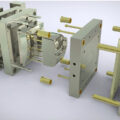
Read more →Clamping System Introduction in Injection Molding Machine – By Zafar Kamal The function of the clamp of the injection molding machine is twofold. The fixed one is called platen and the other one is movable support the two halves of the injection mold and open and close the mold at the appropriate time in the molding cycle. The clamp unit also takes up the pressure applied to the plastic being injected by the injection unit during the injection part of the molding cycle. To oppose the injection pressure necessary to deliver the highly viscous melt to the mold requires a significant amount of force. Without adequate force, the mold would simply open at its parting line and allow the molten material to escape. The result can be a reject part, or a mess which would require down time for clean up, and even more important, it could result in personal injury to the operator or other person in the vicinity.
Read more →Quality Control in Injection Moulding Molds – By Zafar Kamal Each company has a different interpretation of the need for and degree of quality control. Nevertheless, some measure of part usefulness must be made. In one instance it may be quick, visual inspection of the part for appearance only, while on the other hand, laboratory testing may be required to determine dimensional tolerance and other physical properties. Any inspection will add to the cost of the final part but this expenditure will also insure the usefulness of the product and its acceptance by endues customer. It should be considered as part of the cost of doing business. Simple inspection and gage testing is often done right at the molding machine, making the operator directly responsible for the quality of the parts he is producing. where quality control laboratories or inspection facilities exist, it may be necessary to hold all production until it is approved by these facilities before the molded parts may be delivered into inventory or shipped. Because of the nature of some thermoplastics materials,
Read more →Mold Shrinkage in Injection Moulding – By Zafar Kamal Most nonplastic materials show relatively small changes in linear expansion and contraction under the influence of the temperature variation. On the other hand, most plastics exhibits considerable dimensional change due to environmental changes. Perhaps the most significant change in the plastics dimensions occurs with the phase change, causing the greatest concern to mold makers and the mold designers. It also represents a major problem to the injection molder. When going through the normal cycle of solid state to plastic melt and back to solid state plastics exhibit dimensional changes which vary widely from one resin to another. There is no practical way of accurately predicting the exact shrinkage allowance for any plastic material. A concerted effort has been expended during the past few years, particularly by the raw material suppliers to develop meaningful and useful data on the subject of the shrinkage. ASTM ha set up a specification for determining mold shrinkage (D-955). But as with most laboratory determinations, the date developed has little or meaning to
Read more →Additives to the Plastics in Injection Moulding – By Zafar Kamal A wide range of additives may be used into the plastic material before molding to enhance its end-use properties. The most common and the useful ingredient is pigmentation for the coloring of the plastic. The better the color the better will be the sale of the plastic, it means salability rely heavily on color. The pigments can be incorporated in a number of ways. The greatest degree of pigment dispersion is accomplished through compounding, which is performed in separate facilities and is usually the most expensive method. When compounded colors are specified, inventory of the plastic becomes a major concern, especially when a number of colors may be included in the production schedule. The most common and the most widely used method is dry coloring, a procedure carried out completely within the molder’s plant. Finely divided particles of pigment are tumbled with plastic material and adhere to the surface of the pellets through the static charge developed by most resins. In some instances, a
Read more →