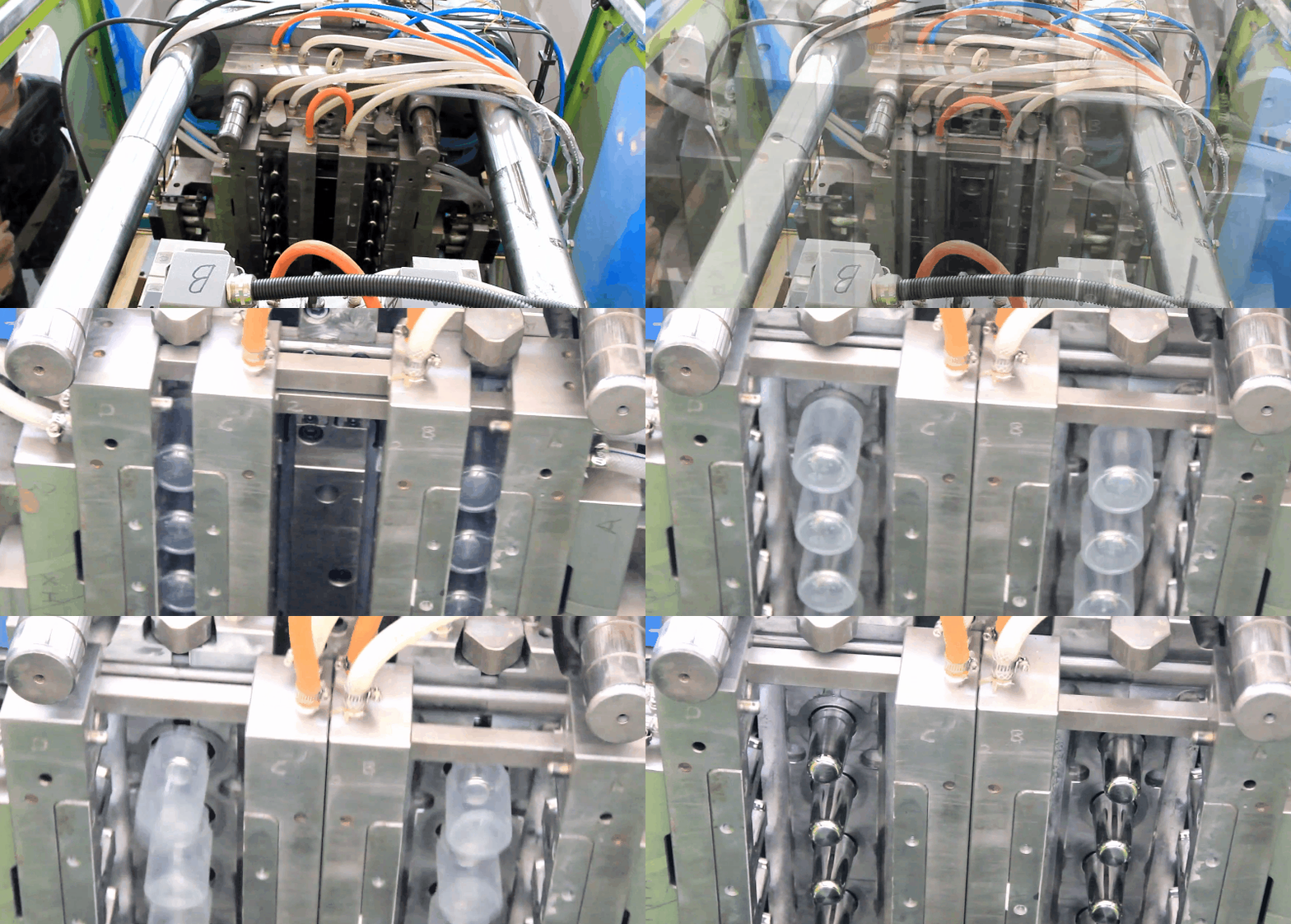
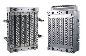
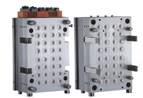
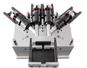
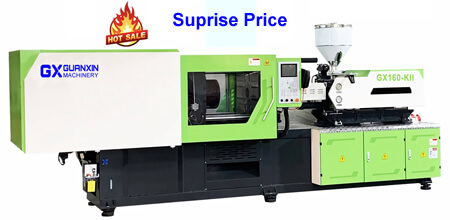
Exhaust System of Toshiba Injection Molding Machines Some material may produce harmful gas, smoke, or dust. In that case, be sure to install an exhaust system on administrator’s responsibility. When working, be sure to wear suitable protection tools, such as helmet, safety glasses or gas mask. The height and safety distance of the protective device with regard to designing of this machine have been calculated using the specified working position (the ground plane of the machine or the working space included in the machine) as a reference surface. If a user requires an additional supplementary working space for the operation of the machine or wishes to increase the machine installation space, the height and safety distance of the related protective device must be calculated again (see the GB 23821 Standards). If further required, the related protective device itself must be additionally provided. Please note that we are not responsible for any trouble that may be caused by modification of the working position of the machine without approval of our company.
Read more →Quality Control in Injection Moulding Molds – By Zafar Kamal Each company has a different interpretation of the need for and degree of quality control. Nevertheless, some measure of part usefulness must be made. In one instance it may be quick, visual inspection of the part for appearance only, while on the other hand, laboratory testing may be required to determine dimensional tolerance and other physical properties. Any inspection will add to the cost of the final part but this expenditure will also insure the usefulness of the product and its acceptance by endues customer. It should be considered as part of the cost of doing business. Simple inspection and gage testing is often done right at the molding machine, making the operator directly responsible for the quality of the parts he is producing. where quality control laboratories or inspection facilities exist, it may be necessary to hold all production until it is approved by these facilities before the molded parts may be delivered into inventory or shipped. Because of the nature of some thermoplastics materials,
Read more →Mold Shrinkage in Injection Moulding – By Zafar Kamal Most nonplastic materials show relatively small changes in linear expansion and contraction under the influence of the temperature variation. On the other hand, most plastics exhibits considerable dimensional change due to environmental changes. Perhaps the most significant change in the plastics dimensions occurs with the phase change, causing the greatest concern to mold makers and the mold designers. It also represents a major problem to the injection molder. When going through the normal cycle of solid state to plastic melt and back to solid state plastics exhibit dimensional changes which vary widely from one resin to another. There is no practical way of accurately predicting the exact shrinkage allowance for any plastic material. A concerted effort has been expended during the past few years, particularly by the raw material suppliers to develop meaningful and useful data on the subject of the shrinkage. ASTM ha set up a specification for determining mold shrinkage (D-955). But as with most laboratory determinations, the date developed has little or meaning to
Read more →Additives to the Plastics in Injection Moulding – By Zafar Kamal A wide range of additives may be used into the plastic material before molding to enhance its end-use properties. The most common and the useful ingredient is pigmentation for the coloring of the plastic. The better the color the better will be the sale of the plastic, it means salability rely heavily on color. The pigments can be incorporated in a number of ways. The greatest degree of pigment dispersion is accomplished through compounding, which is performed in separate facilities and is usually the most expensive method. When compounded colors are specified, inventory of the plastic becomes a major concern, especially when a number of colors may be included in the production schedule. The most common and the most widely used method is dry coloring, a procedure carried out completely within the molder’s plant. Finely divided particles of pigment are tumbled with plastic material and adhere to the surface of the pellets through the static charge developed by most resins. In some instances, a
Read more →Mold Release in Injection Moulding Mold – By Zafar Kamal Mold release is affected by a number of factors. Some molding compounds show better mold release than others, but it has been found that these compounds frequently have other disadvantages, such as greater shrinkage and less gloss. It is easy to understand what gloss has to do with the mold release, resins which develop the grainy or frosty surface will release from the mold better than smooth, high-gloss resins. However, even similar materials may vary in mold release properties. This problem may be alleviated by changing the mold design, or one or more of the molding conditions, without effecting the end properties of the molded part. Mold release may be affected if the mold is packed too tightly in an effort to reduce or control shrinkage. Also , a molded piece may stick if the injection time is too long and the part has shrunk on the core, a problem may be alleviated by reducing the injection time. On the other hand, the cycle may be
Read more →Part Ejection in Injection Moulding Mold – By Zafar Kamal A very important step in the construction of the injection mold is part ejection. It depends upon the geometry of the part and the material from which it may be molded, and a number of other factors, the ejection system can vary in design and the method of the operation. The method which is commonly used is knockout pin method which contact the molded part at its edges, or a flat area, or both, and are mechanically operated when the mold opens to eject the part. As the part becomes more detailed, the may be limited to contacting the runner system and not the part itself. Sometimes pins have blades or bar to provide more contact area, or the part may be lifted from the core by means of the stripper rings. Some molded part requires very finish outlook therefore, air blast is used to remove the molded part from the cavity or core section of the mold. It is also important to consider the type of mold finish being
Read more →Mold Cooling on Injection Moulding – By Zafar Kamal In any consideration of the injection molding process the subject of the mold cooling must not be overlooked. Obviously, if hot polymer is to set up within the mold cavity, the material must be cooled sufficiently to solidify it and allow the molded part to be removed from the mold. This, in essence, is the mold-cooling portion of any cycle, and will vary in time and temperature depending upon the geometry of the part and the choice of thermoplastic material. Mold cooling can be considered as taking place with the mold at any temperature below the inlet temperature of the plastic melt. Most commonly, the mold surface will be maintained at a temperature ranging from 30 to 40 degree F upto 120 to 150 degree F. The successful molder will strive to achieve as uniform temperature across the face of the mold as possible ‘to develop within the mold a uniform shrinkage and thereby reduce the tendency to part warpage. When the injection mold is being designed and constructed, definite consideration
Read more →Molding Cycle Time on Injection Moulding – By Zafar Kamal The important thing to remember, while considering the cycle time is that, once the conditions are set into the controlling instruments of the machine, the identical cycle will be repeated accurately for the duration of the production run or until some effective change has been made. In a typical cycle action is started by closing the safety gate at the die area. As it is closed the gate trips two safety limit switches, one for the machine hydraulic system, the other for the overall electrical system. From this point on, machine operation is automatic. Assuming that the machine is equipped with a hydraulic clamp, oil enters a jackram housed within the main ram, causing the movable platen to advance at high speed but under low pressure. Just before the mold halves make contact, a limit switch is tripped, causing oil to be diverted from the jackram to the main cylinder. Platen speed immediately drops off, but pressure increases. As the mold halves make contact, pressure builds up, sensed by the
Read more →Manual Charging on Toshiba Injection Molding Machines MANUAL charging is necessary before carrying out MANUAL operation, SEMI-AUTOMATIC operation and AUTOMATIC operation. (The following descriptions are given on condition that resin has been supplied and barrel heating up has been completed before starting operation.) Screw Rotation Speed(SRN) 20min-1 Back Pressure (BP) 49MPa (Max. setting) * In order to avoid a problem, Back Pressure (BP) here should be high enough for the screw not to retract during its rotation. Use the operation controller to operate the machine by following the procedure below. [1] Press [MAN] of the OPERATION selector button. [2] Close the safety gate. Then press [INJ] of the SCREW button and move the screw to the advance limit. [3] Continuously press [CHARGE] of the SCREW button to start charging. ※The LED blinks during charging. ※After the LED flicker became from slow to fast, charging continues without pressing [CHARGE] button. [4] After confirming melted resin flowing out of the nozzle, increase (SRN) setting and lower (BP) setting. ※The LED lights after the completion of charging. Feel Free to Contact Us if
Read more →Auxiliary Equipment Precaution of Toshiba Injection Molding Machines (1) We are liable for the interaction between the machine and auxiliary equipment, only when we design the interface for the auxiliary equipment (product take-out robot, mold changer, mold clamp device, mold temperature controller, or conveyor, etc.). (2) When removing a mechanical cover, door or safety device to mount auxiliary equipment, be sure to install the cover or protection device for securing the safe distance to prevent reaching of human body to a dangerous place. Refer to the following table for safety distance. (3) When the auxiliary equipment is dismounted, be sure to restore the original cover, door or safe device originally attached to the machine. (4) The height and safety distance of the protective device with regard to designing of this machine have been calculated using the specified working position (the ground plane of the machine or the working space included in the machine) as a reference surface. If a user requires an additional supplementary working space for the operation of the machine or wishes to increase the machine installation space,
Read more →Timers Setting on Injection Moulding Machines Following the setting of the nozzle controller, set timers on the [INJECT] screen. [1] Setting of injection timer Set filling time of resin into mold cavity added with holding time into injection timer. 1) Touch [INJECT] of [TIMER] on the [INJECT] screen to open the [INJECT] timer setting window. 2) Set the required time in the step switch on the [INJECT] timer setting window. [2] Setting of cooling timer Set the required time for that filled resin is cooled and solidified and become ready for take-out by following tphe procedure the same as of injection timer. In general set the cooling timer so that charge is completed during timer operation. [3] Setting of interval timer Set product take-out time with the mold located at the open limit by the above procedure the same as of injection timer. When inspection and setting of each part is completed, carry out MANUAL charging, MANUAL operation, SEMI-AUTOMATIC operation, and AUTOMATIC operation.
Read more →Nozzle Controller Setting on Injection Molding Machines [1]Selection of nozzle retract timing Nozzle retract timing is selected out of the following four modes on the [INJECT] screen. a. [CONTINUE] (Continuous advance). Operation is carried out with the nozzle kept touched to the mold. b. [AFT COOL] (cooling out). The nozzle retracts on cooling out of every operation cycle. c. [AFT CHG] (charge out). The nozzle retracts on charge out or melt decompression out. d. [AFT INJ] (injection out) The nozzle retracts on injection out. (This is not used generally on the open nozzle.) Set the nozzle mode by following the procedure below. 1) Touch [SPRUE BK] (sprue break) on the [INJECT] screen to open the [SPRUE BK] mode setting window. 2) Select a nozzle mode on the setting window and touch [x] (close) switch. [2] Selection of nozzle retract limit Set the time from nozzle retract start to stop. 1) Touch the [INJECT] screen selector button and the [INJ SET] screen change button, to display the [INJ SET] screen. 2) Touch [NOZZLE RET TIME] (nozzle retract time) on the [INJ
Read more →