Extrusion Blow Molding Technique Introduction
In extrusion blow molding, a parison is formed by an extruder. The plastic pellets are melted by heat which is transferred from the barrel and by the shearing action of the extruder screw as they pass through the extruder. The helical flights of the screw change configuration along its length from input to output ends to ensure a uniformly homogeneous melt.
Turning continuously the screw feeds the melt through the die head as an endless parison or into an accumulator. The size of the part and the amount of the material necessary to produce the part (shot size) dictate whether or not an accumulator is required. The non-accumulator machine offers an uninterrupted flow of the plastic melt.
With the accumulator the flow of the parison through the die is cyclic. The connecting channel between the extruder and the accumulator, and within the accumulator itself, are design rheologically to prevent restrictions that might impede the flow or cause the melt to hang up. Flow part should have low resistance to melt flow to avoid placing an unnecessary load on the extruder. To ensure that the least heat history is developed during processing, the design of the accumulator should provide that the first material to enter the accumulator is the first to leave when the ram empties the chamber; and the chamber should be close to totally emptied on each stroke.
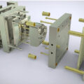
When the parison or tube exits the die and develop a preset length, a split cavity mold closes around the parison and pinches one end. Compressed air inflates the parison against the hollow blow mold surfaces, which cools the inflated parison to the blow mold configuration. Upon contact with the cool mold wall, the plastic cools and set the part shape. The mold opens, eject the part, and closes around the parison to repeat the cycle.
Various techniques are used to introduce air into the parison. It may be accomplished through the extrusion die mandrel, through a blown pin over which the end of the parison has dropped, through blown head applied to the mold, or through blowing needles that pierce the parison. The wall distribution and the thickness of the blown part are usually controlled by parison programming, blow ratio, and the part configuration.
The mold clamping methods are hydraulic and / or toggle actuation. Sufficient daylight in the mold platen area is required to accommodate parison system, unscrewing equipment.
Clamping system vary based on the part configuration. Basically there exist three types. The “L-shape” has the printing line at an angle of 90 degrees to the center line of the extruder. The “T-shape” has the parting line inline with the extruder center line. Mold opening is perpendicular to the machine center line. The third method is the gantry type. The extruder/die unit is arranged independently of the clamping unit. This arrangement permits the clamp to be positioned in either the “L” or “T” shape without being tied directly into the extruder.
The basic extrusion blow molding machine consists of an extruder, crosshead die, clamping arrangement, and mold. Variations include multiple extruders for co-extrusion of two or more materials, parison programmer to shape the parison to match complex blown part shapes, and the multiple station clamp systems to improve output through the use of the multiple molds.
– By Zafar Kamal