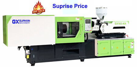
3 / 6 Month and One-year Maintenance Checklist for Injection Molding Machines 3 Months Maintenance Checklist for Injection Molding Machines Timing belt (For inspection method, refer to section 6.2 Timing Belt Inspection) a. Check that the timing belt is not loose. b. Check that the belt and pulley have no wearing or damage. 6 Months Maintenance Checklist for Injection Molding Machines 1. In consideration of service lives of screw tip assembly, packing, and electric equipments (heater, timers), make preparation for replacement. The guarantee period for these equipments is six (6) months. 2. Inspect fans inside the control cabinet for rotating normally. And inspect fans for existence of abnormal noise or insulation status. DANGER: Securely turn off the power and measure voltage at inspection points to check power off before inspection. 3. Lubrication One Year Maintenance Checklist for Injection Molding Machines Inspect the inside bearing in operation of the clamp unit, ejection device, mold thickness setter, injection unit, nozzle touch drive unit for existence of abnormal noise or for wearing on bushing and sliding face of slide ways. Feel Free to
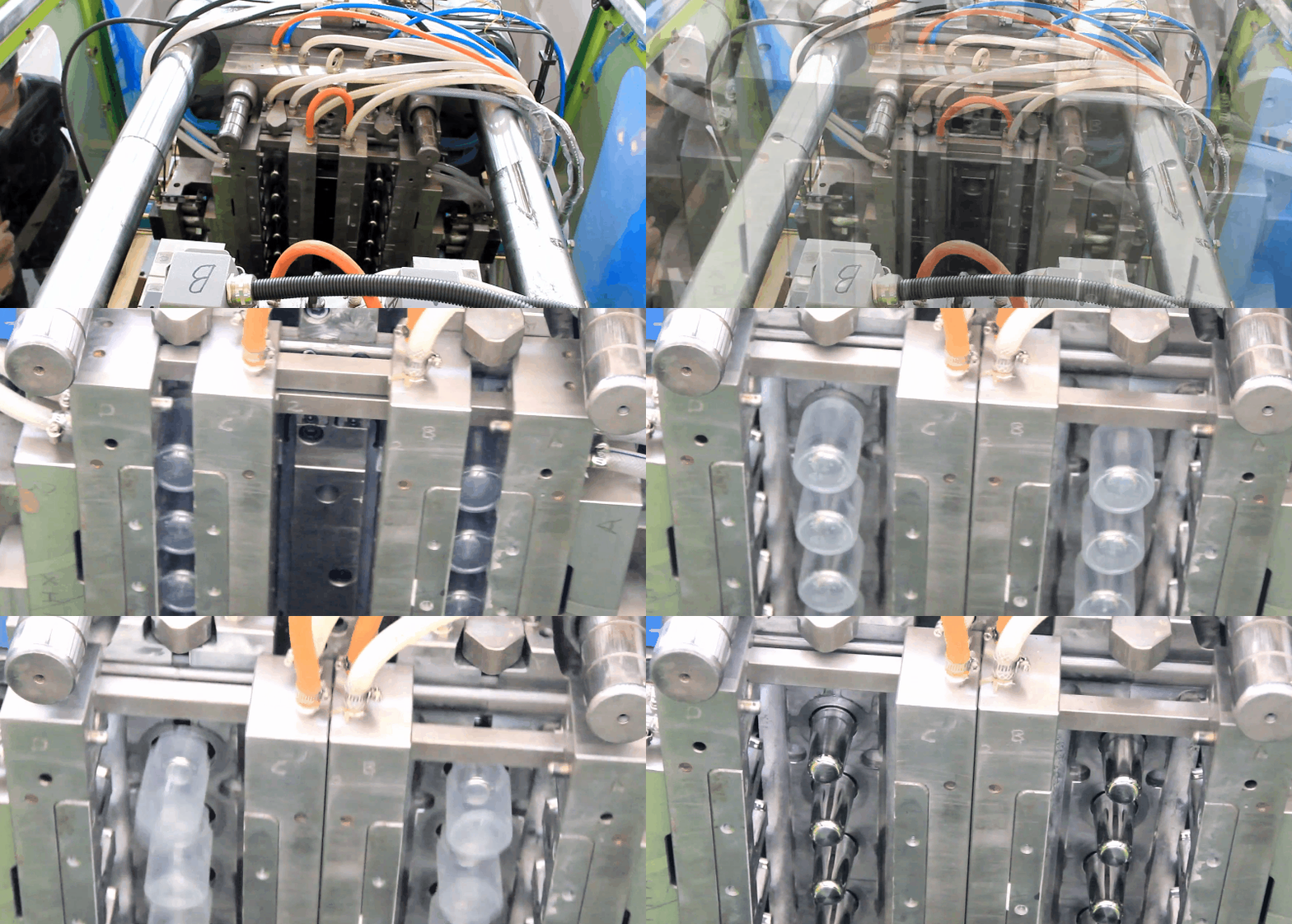
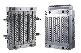
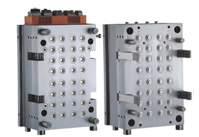
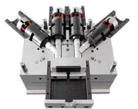
Read more →Injection Molds in Injection Molding Machines An injection mold consists of two halves into which the impression of the part to be moulded is cut. The mating surfaces of the mould halves are accurately machined so that no leakage of the plastic can occur at split line. If leakage does occur the flash on the moulding is unsightly and expensive to remove. In order to facilitate mounting the mould in the machine and cooling and ejection of the moulding, several additions are made to the basic mould halves. 1. Backing plates permit the mould to be bolted on to the machine platens. 2. Channels are machined into the mould to allow the mould temperature to be controlled. 3. Ejector pins are included to that the moulded part can be freed from the mould. The mould cavity is joined to the machine nozzle by means of the sprue. The sprue anchor pin then has the pulling the sprue away from the nozzle and ensuring that the moulded part remains on the moving half of the mould, when the mould opens. For
Read more →Extrusion Blow Molding Technique Introduction In extrusion blow molding, a parison is formed by an extruder. The plastic pellets are melted by heat which is transferred from the barrel and by the shearing action of the extruder screw as they pass through the extruder. The helical flights of the screw change configuration along its length from input to output ends to ensure a uniformly homogeneous melt. Turning continuously the screw feeds the melt through the die head as an endless parison or into an accumulator. The size of the part and the amount of the material necessary to produce the part (shot size) dictate whether or not an accumulator is required. The non-accumulator machine offers an uninterrupted flow of the plastic melt. With the accumulator the flow of the parison through the die is cyclic. The connecting channel between the extruder and the accumulator, and within the accumulator itself, are design rheologically to prevent restrictions that might impede the flow or cause the melt to hang up. Flow part should have low resistance to melt flow to avoid placing an
Read more →Blow Molding Techniques Introduction Hollow plastics products such as a squeeze bottles, milk bottles, fuel tanks, toys, oil containers, chemical tanks, furniture, electrical housing, are blow moulded. Different processes are used but basically all of them are similar. The basic process involves producing a plastic parison or preform (tube, pipe, or test tube plastic shape), placing this preform into a closed two plate mold, injection of air into the heated parison to blow it out against the mold cavity, cooling of the expanded parison, opening of the mold, and removing the rigid blow molded part. Blow molding technique basically divided into three categories, namely, the extrusion blow molding process which principally uses as unsupported parison, and the injection blow molding process which uses a preform supported on a metal core pin. The third major category is called the stretch-blow molding process. Stretch-blow molding can be started with either the extrusion or injection blow molding process. By stretching at prescribed temperature the properties of many plastics can be significantly improved providing cost / performance advantages. These processes provide different advantages to
Read more →Inspection Prior to Operation of Toshiba Injection Molding Machines Check the following items daily before the operation to regularly operate the machine efficiently and for safety. 1. Safety device 1). Safety gate on the operation side. (Check the electrical safety device ) a. Open the movable platen to the open limit. b. Close the movable platen until the hook of the mechanical safety device meets the crest on the rod. c. Press [MAN] of the OPERATION selector button and open the safety gate by 30 mm [1.18 in] or more. d. Press [CLOSE] and [OPEN] of the MOLD buttons. (Check that the movable platen does not close or open.) 2). Mechanical safety device a. Open the movable platen until the hook of the mechanical safety device meets the groove on the rod. b. Open the safety gate on the operation side sufficiently. (Check that the hook of safety device fits into the groove on the rod.) 3). Purge shield (Check the electrical safety device.) a. Press [MAN] of the OPERATION selector button and open the safety gate by 30 mm
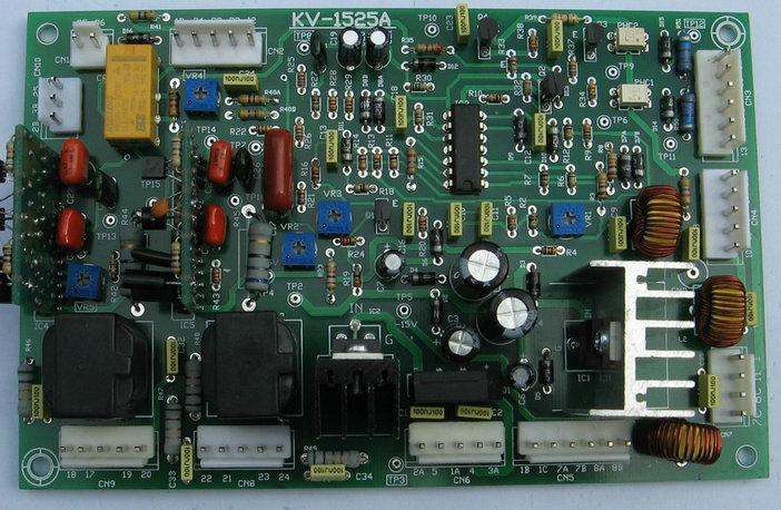
Read more →Prohibited Operations on Toshiba Injection Molding Machines Daily inspection and maintenance are essential to make the injection molding machine operate at its designed potential and to maximize its service life. However, the following operations regarding maintenance and modification of the machine should not be attempted by the user. Please observe these restrictions. 1. Clamp Unit 1) Disassembly and repair of ball screw 2) Replacement of timing belt and pulley 3) Removing and setting of gears on mold thickness setter 2. Injection Unit 1) Disassembly and repair of load cell 2) Disassembly and repair of ball screw 3) Replacement of timing belt and pulley 3. Electric Components 1) Disassembly and repair of servomotor 2) Disassembly and repair of geared motor 3) Disassembly and repair of PC board 4) Modification and addition of electric circuit 4. Frame 1) Welding and drilling onto the frame
Read more →Monthly Maintenance Checklist for Injection Molding Machines Feel Free to Contact Us if Any Questions
Read more →Daily Inspection of Injection Molding Machines The operator should check the following items every day in machine operation.
Read more →Weekly Inspection on Injection Molding Machines The operator should check the following items weekly in machine operation.
Read more →Purge Shield of Toshiba Injection Molding Machines 1) Outline In case of the resin is purged (The injection unit is made to retreat from mold touch position for the resin purging out), this device works as the dangerous prevention cover when resin is flew all over the place. 2) Interlock The purge shield is set up limit switch (LS1Z) for the cover closing limit detection. If the purge shield is opened, all operation (injection, charging, the nozzle advance and retract, mold opening and closing, ejection, etc.) is not possible except the swiveling of the injection unit. 3) Notes It is not possible to swivel the injection unit without opening the purge cover. Please open the purge shield when you swivel the injection unit.
Read more →Precautions before Operating Toshiba Inejction Molding Machines (1) Read this manual before operating. (2) Keep this manual for future reference. (3) Secure installation space around the machine according to the foundation drawing. (4) Connecting the power source. Strictly observe the following ordinances of the Ministry of Economy, Trade and Industry when installing the injection molding machine inside Japan. a) Grounding work The customer’s personnel who are qualified to perform such work shall perform grounding work. See the table below for installation resistance for the grounding. And also, please connect a metallic body of peripherals with the machine main earth bar (pole) at the same time. b) Installation of circuit breaker Install a circuit breaker in the electric line of this injection molding machine. Locate this circuit breaker on the power side of or inside the power switchboard. It is recommended that a medium-sensitivity, high-speed type (100 mA) circuit breaker to meet inverter be equipped. (5)Power source voltage Power source voltage fluctuation must be maintained within 10 % range of rated value. (6)Cooling water For the quantity of required cooling water,
Read more →Electrical Control system on Injection Moulding Machines – By Zafar Kamal The electrical control system serves as the nerve and memory center to program and sequence the machine cycles. Its purpose is to sense, program the results, and cause an action to take place. Position is sensed through the use of the limit switches, change in the heat through thermocouples, and changes in pressure through pressure switches. After analyzing the incoming signals and making a programmed decision, the control system passes this decision on to the pilot operating devices which convert the electrical signal into mechanical motions, thus resulting in the desired action. There are specific type of the devices available for the different functions. First, There is motor or prime mover , and then the sensing devices, next, control systems such as motor starters, heater contractors and relays, and finally , the ultimate load controls such as solenoids or heater bands. The electric motor or motors used in the average injection press must have a high breakdown torque. Most motors operate on 220 or 440
Read more →