Injection and Charge Controller Setting on Injection Molding Machines
[1] Setting of charge stroke [LS5]
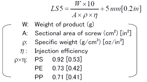
Set necessary data matched to injection weight on [LS5] (charge out position) on the
[INJECT] screen of INJECTVISOR. Set value is obtained by the required stroke calculated
from product weight (W) added with 5 mm [0.2 in] of cushion amount.
Setting value:
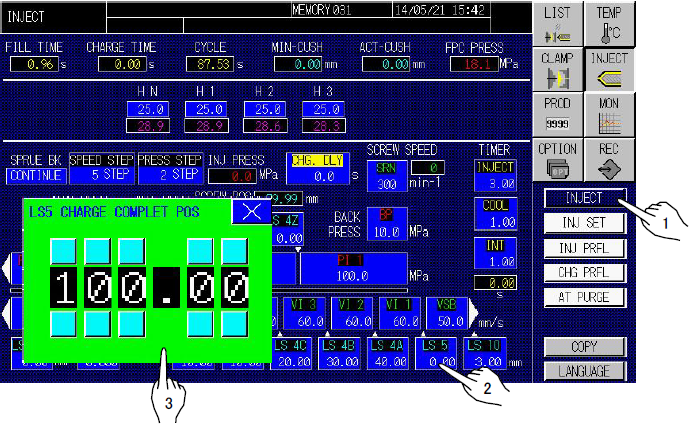
1) Touch the [INJECT] screen selector button and the [INJECT] screen change button, to display the [INJECT] screen.
2) Touch [LS5] (charge out) switch on the [INJECT] screen to open the [LS5 CHARGE COMPLET POS] window.
3) Set the prescribed value on the window.
[2] Setting of melt decompression amount [LS10]
Set melt decompression amount [LS10] to the minimum value where resin will not leak from the nozzle if an open nozzle is utilized.
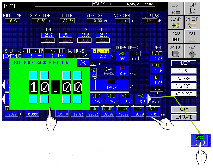
1) Following the setting of [LS5], touch [LS10] (melt decompression amount) switch on the [INJECT] screen to open the [LS10] window.
2) Set 2 – 3 mm [0.08 – 0.12 in] of melt decompression amount in the step switch on the window.
[3] Setting of melt decompression speed VSB
Set melt decompression speed VSB on the [INJECT] setting screen.
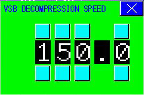
1) Following the setting of [LS10], touch [VSB] key on the [INJECT] screen to open the [VSB DECOMPRESSION SPEED] setting window.
2) Set data, generally 20 – 50 mm/s [0.8 – 2.0 in/s], in the step switch on the window.
[4] Setting of shift to hold position [LS4]
1) Set 10 mm [0.4 in] in [LS4] (shift to hold position) and adjust [LS4] together with [LS5] (charge out position). Determine the position where mold cavity is filled with melted resin as shift to hold position. Give a cushion to the screw so that the forward limit by holding pressure does not stand on the screw advance limit. (Make setting to locate the screw position at injection completion 2 – 3 mm [0.08 – 0.12 in] before advance limit.)
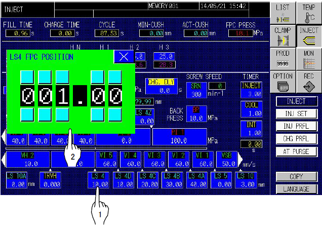
a) Followingthe setting of [VSB], touch [LS4] key on the [INJECT] screen to open the [LS4 FPC POSITION] window.
b) Set the prescribed value on the setting window.
2) In PLASTIC mode of FPC PRESS
a) Touch [FPC PRESS] key on the [INJ SET] window.
b) Touch [PLASTIC] key for changing to the “PLASTIC” mode.
Please set the Injection “SPEED” more than 2 steps.
* If one-step filling is to be performed, set LS4A at a position ahead of the FPC position, and set “VI2” to the same value as for “VI1”. These settings allow the holding pressure to be shifted by means of resin pressure.
[5] Setting of injection speeds [VI1] – [VI5] and [VH1]
Injection speed consists of the filling speed in the stage melted resin is filled in the mold
cavity and the holding speed in the stage of holding accompanied by shrinkage due to
cooling and solidifying before gate sealing. Set injection speeds [VI1] – [VI5] and [VH1] on
the [INJECT] screen.
1) The setting of filling speeds [VI1] – [VI5]
Touch [VI1] – [VI5] (injection speeds) on the [INJECT] screen to open injection speed setting windows. Set filling speeds in [VI1] – [VI5] successively in the step switch on the setting windows, starting from a low speed of about 50 mm/s [2.0 in/s] gradually increase it depending on product profile. Set [VI5] to 10 – 40 mm/s [0.4 – 1.6 in/s] to accurately control holding position.
2) The setting of holding speed [VH1]
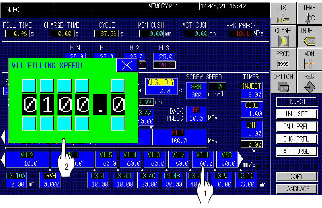
Touch [VH1] (holding speed) on the [INJECT] screen to open the [VH1 FILLING SPEED1] setting window. Set 10 – 30 mm/s [0.4 – 1.2 in/s] of holding speed in the step switch on the setting window.
1) The machine uses units of speed in mm/s while the machine controlled by hydraulic
pressure uses units of speed in %.
2) Graphs of setting value and injection speed for the machine controlled by hydraulic
pressure are shown for reference in Section 5.
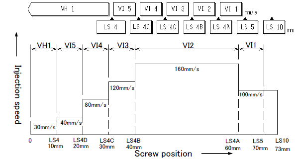
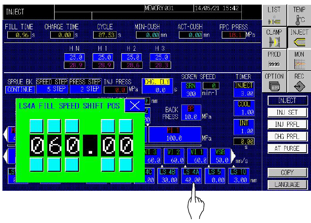
[6] Setting of speed shift positions [LS4A], [LS4B], [LS4C] and [LS4D]Touch [LS4A] – [LS4D] (speed shift positions) on the [INJECT] screen to open the setting windows. Set speed shift positions successively in the step switches on [LS4A] – [LS4D] windows. For [LS4D], set the value of shift to hold position [LS4] added with 5 – 15 mm [0.2 – 0.6 in].
For [LS4A], [LS4B], and [LS4C], set the data depending on mold profile.
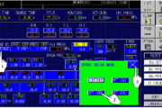
An example of setting and procedure are shown bellow.
[7] Setting of injection pressures [PI1], [PH1] – [PH4]
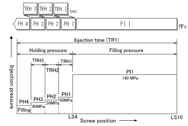
Injection pressure consists of filling pressure (primary pressure) in the stage melted resin is filled in the mold cavity and the holding pressure (secondary pressure) in the stage of holding accompanied by shrinkage due to cooling and solidifying before gate sealing. Continued from [LS4A] – [LS4D], set injection pressures [PI1], [PH1] – [PH4] on the [INJECT] screen.
1) Set filling and holding pressures by means of resin pressure (MPa
2) Do not set 1.5 MPa <15 kgf/cm2> [218 psi] or lower pressure.
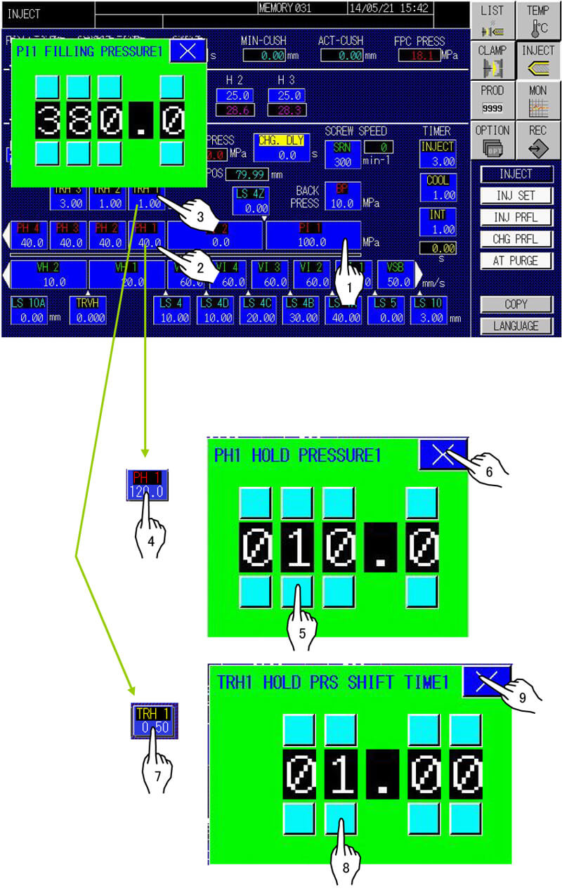
1) Setting of filling pressure [PI1]
Touch [PI1] (injection pressure) on the [INJECT] screen to open the [PI1] setting window. Set filling pressure in the step switch on the setting window, starting from lower level and gradually increase it to higher pressure slightly exceeding the actual filling pressure.
2) Setting of holding pressures [PH1] – [PH4]
Touch [PH1] – [PH4] (injection pressure) on the [INJECT] screen to open the setting windows. Set holding pressures successively in the step switches on [PH1] – [PH4] setting windows, starting from 20 – 40 MPa <200 – 400 kgf/cm2> [2900 – 5800 psi] and gradually increase them to an optimum pressure.
3) Setting of holding timers [TRH1] – [TRH3]
Touch [TRH1] – [TRH3] (holding timers) on the [INJECT] screen to open windows. Set 1 – 2 sec of holding times successively in the step switches on [TRH1] – [TRH3] setting windows.
1) Set injection pressure by means of resin pressure (MPa
2) Graphs of setting value and injection pressure for the machine controlled by
hydraulic pressure are shown for reference in Section 5.
An example of the final setting and procedure is shown bellow.
[8] Setting of screw back pressure [BP]
Following the setting of injection pressure, set screw back pressure on the [INJECT] screen.
1) Setting of screw back pressure [BP] Touch [BP] (screw back pressure) of [BACK PRESS] on the [INJECT] screen to open the [BPF BACK PRESS] setting window. Set back pressure data in the step switch on the [BP] setting window, generally in the range of 4 – 20 MPa <40 – 200 kgf/cm2> [580 – 2900 psi].
a). Set screw back pressure by means of resin pressure (MPa
b). Do not set 1.5 MPa <15 kgf/cm2> [218 psi] or lower pressure.
c). Graphs of setting value and injection pressure for the machine controlled by hydraulic pressure is shown for reference in Section 5.
2) Check of screw back pressure [BP] Check screw back pressure with [INJ PRESS] during charging.
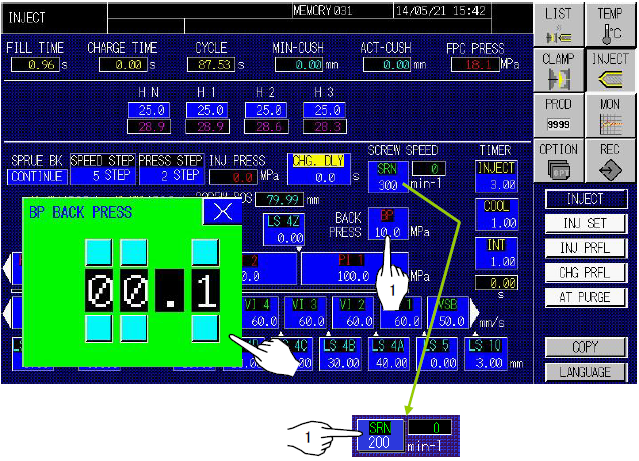
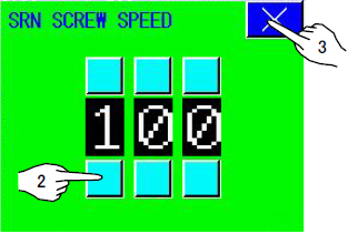
1) Setting of screw speed [SRN] Touch [SRN] (screw speed) of [SCREW SPEED] on the [INJECT] screen to open the [SRN SCREW SPEED] setting window. Then set the screw speed (min-1).
2) Check of screw speed [SRN] Check screw speed with [SRN] during charging.
