Adjustment and Setting of Clamp Controller on Toshiba Injection Molding Machine
1. Setting of Clamping Force and Low Clamping Force
[1] Press [SERVO] of the PREPARATION button on the operation controller to turn on the servomotor.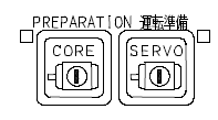
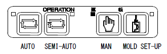
[2] Press [SET-UP] of the OPERATION selector button on the operation controller.
[3] Setting of low-pressure clamp force PCL
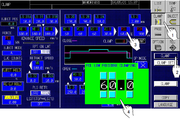
1) Change the INJECTVISOR screen to [CLAMP].
2) Press the [CLAMP] screen selector button and the [CLAMP] screen change button to display the [CLAMP] screen.
3) Touch [PCL] (low-pressure clamp force) on the screen to open the [PCL LOW PRESSURE CLAMPING] setting window.
4) Set the lowest clamping pressure (PCL) to enable mold opening/closing and mold closing smoothly while actually opening and closing the mold platen.
After setting of low-pressure clamp force, set clamp force on the same screen.
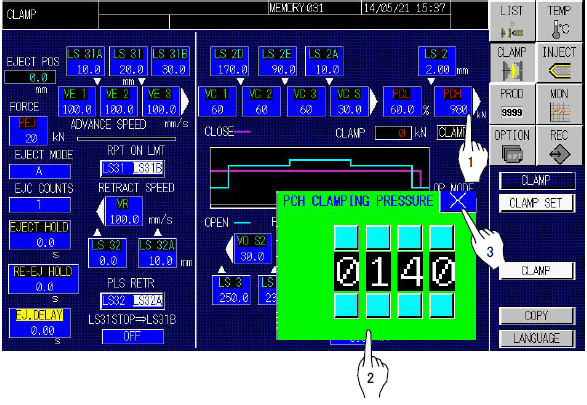
1) Touch [PCH] (clamp force) on the [CLAMP] screen to open the [PCH CLAMPING PRESSURE] setting window.
2) Set the required clamp force (kN
3) Touch [] (close) to close the window.
NOTE: Be sure to carry out die height adjustment when clamp pressure setting is changed.
(For details, refer to the section 2.4.3[8] of this manual.)
2. Setting of Mold Open/Close Speed and Speed Shift Position
[1] Press [SET-UP] of the OPERATION selector button on the operation controller.
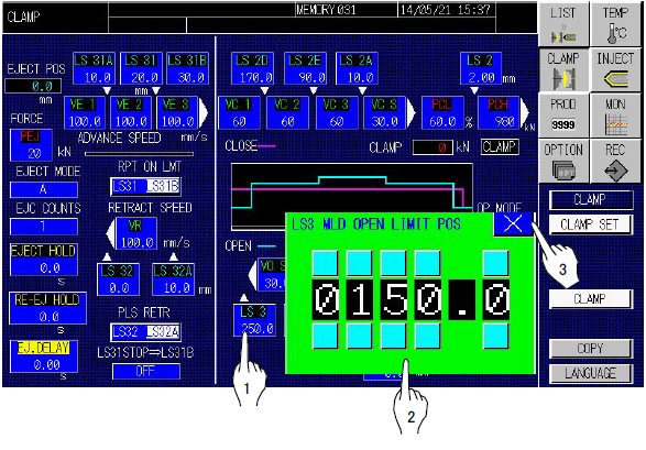
1) Touch [LS3] on the [CLAMP] screen to open the [LS3 MLD OPEN LIMIT POS] setting window.
2) Set the maximum mold open stroke in the step switch of the setting window.
3) Touch [x] (close) to close the window.
* The maximum mold open stroke may be changed according to the specification of the machine. Refer to the attached drawing, MOLD MOUNTING SPACE for checking.
[3] Mold openingContinuously press [OPEN] of the MOLD button on the operation controller to stop the mold at the position suitable for product take-out.
 [4] Check for product take-out space
Check that the product can be automatically dropped or taken out by the take-out robot from the space between the stationary and movable molds.
 [5] Setting of mold open limit [LS3]
Set the dimension shown on [PLATEN POPS] display into the step switch on the [LS3 MLD OPEN LIMIT POS] window on the [CLAMP] screen. For setting follow the procedure of temporary setting.
[5] Setting of mold open limit [LS3]
Set the dimension shown on [PLATEN POPS] display into the step switch on the [LS3 MLD OPEN LIMIT POS] window on the [CLAMP] screen. For setting follow the procedure of temporary setting.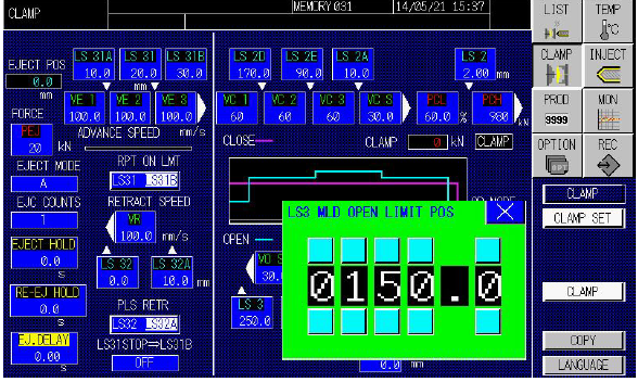 [6]Temporary setting of mold close speed shift positions [LS2A], [LS2D] and [LS2E]
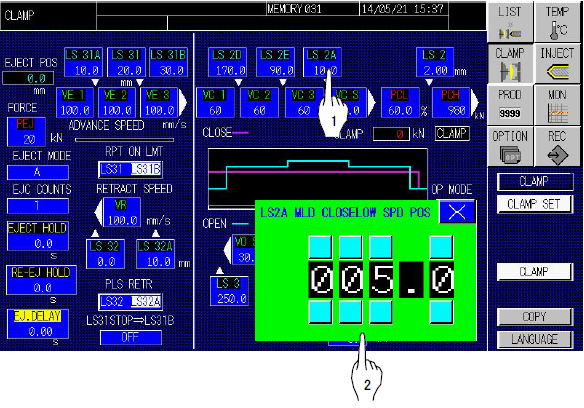
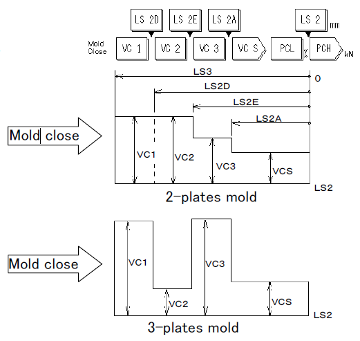
Set the mold close speed shift positions [LS2A], [LS2D] and [LS2E] in the step switch on each setting window opened on the [CLAMP] screen by following the procedure below.
[6]Temporary setting of mold close speed shift positions [LS2A], [LS2D] and [LS2E]
Set the mold close speed shift positions [LS2A], [LS2D] and [LS2E] in the step switch on each setting window opened on the [CLAMP] screen by following the procedure below.1) Set 10 mm [0.4 in] in [LS2A] (shift position from fast mold close VC2 to slow close VCS) (low pressure) as the initial value.
2) Set 2/3 position between [LS2A] and [LS3] into [LS2D] (shift position from fast mold close VC1 to VC2) and also 1/3 position between [LS2A] and [LS3] into [LS2E] (shift position from fast mold close VC2 to VC3) as the initial values.
Example with 250 mm [9.8 in] set into [LS3]
Set value of LS2E = (LS3 – LS2A)/3 + LS2A
= (250 – 10)/3 + 10 = 90
[9.8in] [0.4in] [0.4in] [3.5in]
Set value of LS2D = (LS3 – LS2A)/3 + LS2E
= (250 – 10)/3 + 90 = 170
[9.8in] [0.4in] [3.5in] [6.7in]
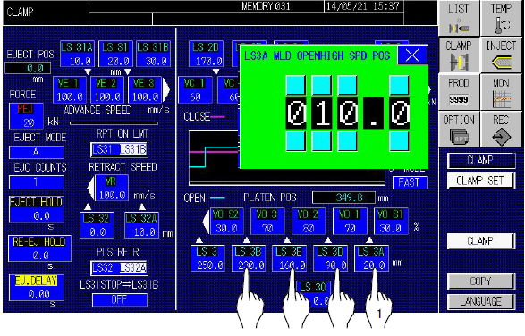
1) Set 20 mm [0.8 in] into [LS3A MLD OPENHIGH SPD POS] (shift position to fast open speed) as the initial value.
2) Set the value, LS3 set value – 20 mm [0.8 in], into [LS3B] (shift position from fast mold open VO3 to slow open VOS2) as the initial value.
Example with 250 mm [9.8 in] set into [LS3]
Set value of LS3B = LS3 – 20 = 250 – 20 = 230
[0.8in] [9.8in] [0.8in] [9.0in]
3) Set 1/3 position between [LS3A] and [LS3B] into [LS3D] (shift position from fast mold open VO1 to VO2) and also 2/3 position between [LS3A] and [LS3B] into [LS3E] (shift position from fast mold open VO2 to VO3) as the initial values.
Example with 250 mm [9.8 in] set into [LS3]
Set value of LS3D = (LS3B – LS3A)/3 + LS3A
= (230 – 20)/3 + 20 = 90
[9.0in] [0.8in] [0.8in] [3.5in]
Set value of LS3E = (LS3B – LS3A)/3 + LS3D
= (230 – 20)/3 + 90 = 160
[9.0in] [0.8in] [3.5in] [6.3in]
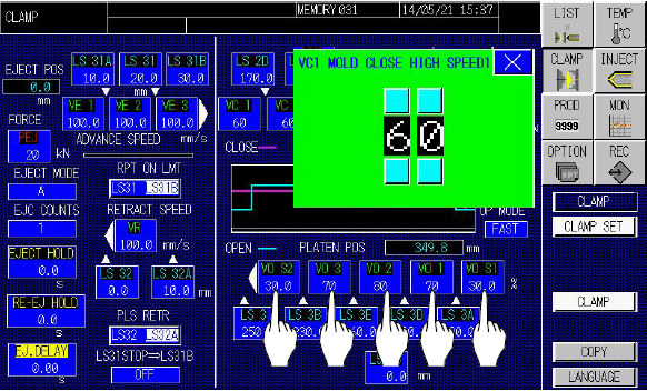
1) Set 60 % in [VC1], [VC2] and [VC3] (fast mold close speeds).
2) Set 30 % in [VCS] (slow mold close speed).
1) Set 60 % in [VO1], [VO2] and [VO3] (fast mold open speeds).
2) Set 30 % in [VOS1] and [VOS2] (slow mold open speeds).
[11] Adjusting of mold open/close speedsWhile opening and closing the mold, gradually increase the temporarily set mold open/close speeds [VC1] ~ [VCS] and [VO1] ~ [VOS2]. Lower [LS2D] and increase [LS3D]. Minimize mold open/close time to the extent no shock is given.
[12] [LS2A] setting
Gradually lower the [LS2A] value set temporarily to an optimum value. [13] [LS3B] setting
Gradually lower the [LS3B] value set temporarily to the extent no shock is given at the mold open limit. [14] Final adjusting
Finally adjust [12] and [13] for final *** setting.
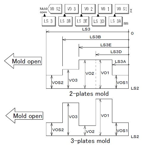
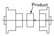
The figures above show examples of setting. In the case of three-piece mold as shown in [Mold open/close speed diagram] on the right, speed setting in consideration of mold opening the intermediate mold is possible.
![With ejector [A] circuit used in setting on injection molding machine](https://alleycho.com/wp-content/uploads/2019/12/With-ejector-A-circuit-used-in-setting-on-injection-molding-machine-180x120_c.png)